Power Quality at Glance
Power Quality:
Power quality is related to the quality of power being supplied or consumed. It is maintained when:
- The State Electricity Board (EB) or Utility provides sinusoidal voltage at rated magnitude and rated frequency to its consumers
- Consumers draw sinusoidal current that is in-phase with the input supply voltage.
EB can assure power quality from their side only when its consumers do meet certain power quality standards (such as, IEEE 519-1992 and/or IEEE 519-2014). Recently, several EBs across the globe have started imposing strict regulations on quality of current, a customer can draw from the supply lines to maintain a healthy power distribution system.
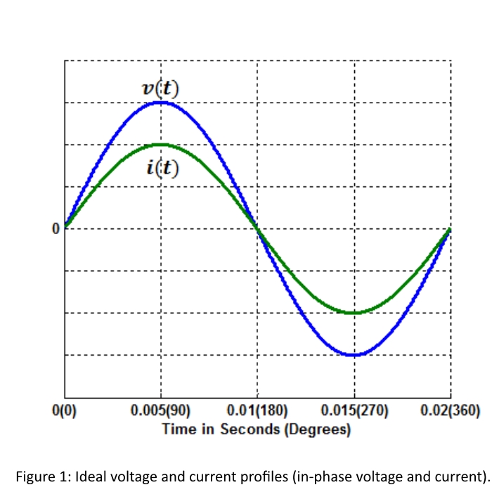
Ideally, the input supply voltage and load current should have the following characteristics
- Voltage: rated magnitude with sinusoidal wave shape and rated frequency
- Current: sinusoidal wave shape at fundamental frequency and in-phase with the voltage
The above requirements can be illustrated as shown in the graph:
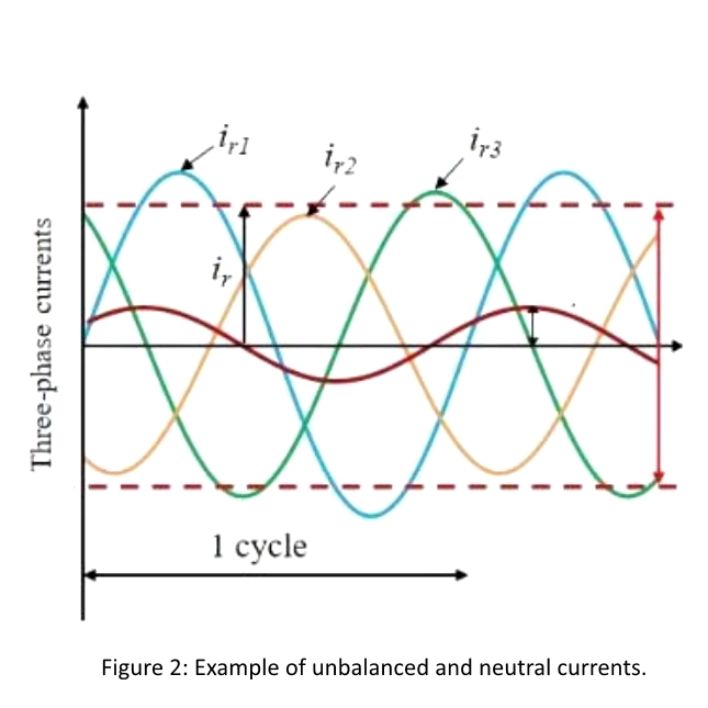
Major Power Quality Issues Related to Load Currents:
- Unbalanced Load Currents and Excessive Neutral Current
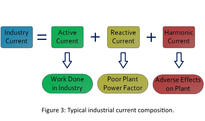
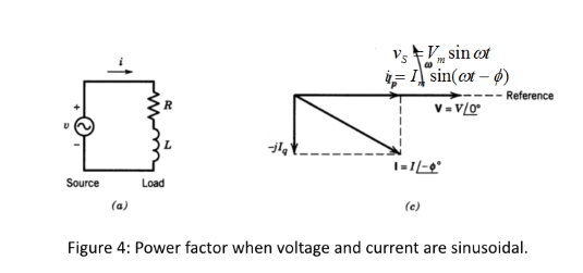
- Low Power Factor (LT Side and HT Side)
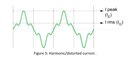
- Harmonics